CWU | MET
CONSTRUCTION OF DEVICE & METHODS USED
The design of the AutoJack’s powertrain was conceived after researching hazard reduction. The goal here was to completely remove the user from the vehicle lifting/securing process, and thereby, removing the hazard. A power source that can smoothly deliver the necessary power to lift a vehicle in the set requirements was needed. After researching and using an engineering decision matrix, hydraulic technology became the obvious choice. The section below how each component of the design will be manufactured and/or purchased, and then assembled. Please see the attached photos (below) for documentation of the "link arm insert" construction progress.
Link Arm Insert: Construction
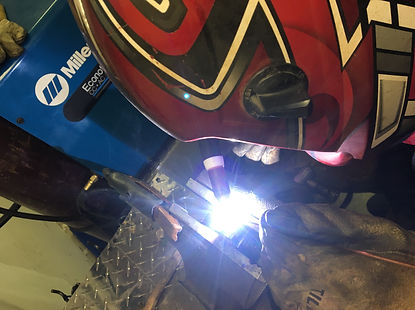
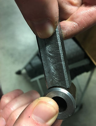
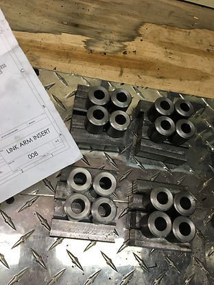
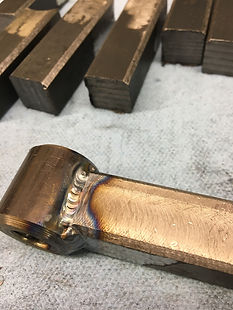
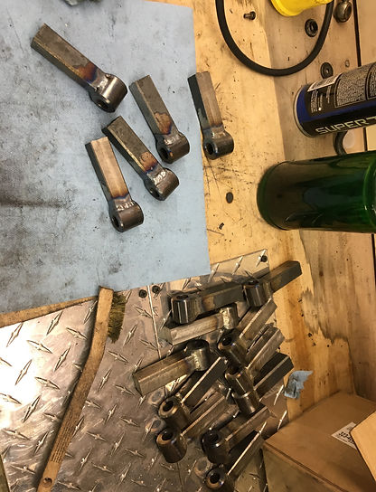
The link arm insets are a critical component of the AutoJack that are responsible for converting horizontal motion into vertical motion. This sub-assembly must be custom machined, since it is a specialized part. The insert consists of two separate parts; the "peg" and "sleeve". For the pegs, raw 1020 steel square stock will be purchased from Metal Supermarkets in Kent, WA. It will then be mounted in a bandsaw and cut to the desired 2.33inch length, creating 16 pegs. The faces of each peg will then be mounted in a vice and milled down for smooth fitment within each link arm. Finally, using a 1" end mill bit, one end of each peg will be notched. For the the sleeve, raw round stock will be purchased from Metal Supermarkets in Kent, WA. It will then be mounted in a vice and cut to the desired 1.25inch length using a table saw. The ends of each sleeve will then be faced on the lathe down to 1.0inch, chamfered, and deburred using the bench grinder. Finally, the notched peg and sleeve can be welded together to create the finished link arm insert.
Hydraulic Cylinder: Purchase
The hydraulic cylinder is another critical component of the AutoJack. It is responsible for translating fluid flow into liner motion. This sub-device must be purchased, since its design is a project in itself. Several analyses (reference “APPENDIX A”) have been performed to determine the necessary requirements that the hydraulic cylinder must fulfil. Using these requirements as a checklist, the appropriate cylinder was located and purchased from the NorTrac product catalog.
Cylinder Cross Rods: Construction
The cylinder cross rods are another critical component of the AutoJack. They are composed of ½ inch diameter, AISI 1020 steel round stock. The raw round stock will be purchased from Metal Supermarkets in Kent, WA. It will then be mounted in a vice and cut to the desired 10inch length using a table saw. The ends of each cross rod will then be faced on the lathe and deburred using the bench grinder. The Bridgeport End Mill, drill guide, and hole jig will then be used to correctly place the necessary cotter pin holes.
Cylinder Pins: Construction
The cylinder pins are another critical component of the AutoJack. They are composed of ½ inch diameter, AISI 1020 steel round stock. The raw round stock will be purchased from Metal Supermarkets in Kent, WA. It will then be mounted in a vice and cut to the desired 4inch length using a table saw. The ends of each cross rod will then be faced on the lathe and deburred using the bench grinder. The Bridgeport End Mill, drill guide, and hole jig will then be used to correctly place the necessary cotter pin holes.
Note: For more Part Construction descriptions, please see the "METHODS AND CONSTRUCTION" section in the linked MET489A-C Report.
Link Arm Insert - Construction - Photo Documentation:


Manufacturing Issues:
"Link Arm Insert" (LAI) Construciton
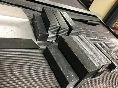
The link arm inserts are a critical component of the AutoJack. They are composed of two separate sub-parts: the “LAI peg” and “LAI sleeve”. For this M/C02, manufacturing details regarding the “LAI sleeve” will be discussed. The sleeves (16) are made from AISI 1020 CR, 1” tube. The raw material was purchased from Metal Supermarkets in Kent, WA. The raw material (24in) was mounted in a vice and a roughing cut of 1.25inches was taken using a table saw. Afterwards, the section was mounted in a three-jaw lathe, and each end of the sleeve was faced down 0.125inches, bringing the sleeves overall length down to 1.00inch +/- 0.003in. Then, each end of the sleeve was chamfered 45 degrees to a depth of 0.05inches. Finally, the fully machined part was de-burred using a bench grinder/wire brush. This process was then repeated a total of 16 times in order to produce 16 fully machined LAI sleeves.
There were two manufacturing issues when producing this part. Firstly, when rough-cutting each sleeve off of the raw material, the saw blade had un-desired horizontal wobble from being worn. This caused each sleeve to come out with a different length, ranging from 1.10in – 1.40in. This was only discovered once all 16 sleeves had been rough cut and were re-measured. Looking ahead, this would cause poor (or impossible) fitment and clearance with the other pinned parts of the AutoJack.
The second issue when producing each LAI sleeve was encountered when attempting to assemble the completed sleeves with the other components of the AutoJack. When designed, the sleeve was intended to have an inner diameter of 0.50inches. Due to the nature of “drawn over mandrel” manufacturing, the produced ID was actually closer to 0.45inches. Looking ahead, this would prevent fitment with the other pinned parts of the AutoJack.
In order to resolve these manufacturing issues, extra out-of-class time was allotted to the project and additional care was taken to correct and ensure the quality of each part. For the inconsistent rough cutting of the sleeves, each sleeve was carefully re-measured and then machined down to the desired 1.0inch length by hand, and one at a time. Since the initial plan was to utilize an automated machining program (that assumes the starting length of all parts to be uniform), this change added significant time to the production of these parts. However, the end result was 16 high quality, 1.00inch +/- 0.003in LAI sleeve parts.
For the out of spec ID of each sleeve, Mathew Burvee was sought out for his machining experience and wisdom. Mr. Burvee suggested using a ½” reamer bit to remove the excess material and create a true ½” hole. This worked perfectly, and the reamed sleeves fit their mating components perfectly. These manufacturing issues have been fully resolved, and the AutoJack project remains on schedule.
AutoJack Device Modification - Lift System Stability
Link Arm Insert (LAI) Moon Gear MOD - Construction - Photo & Video Documentation:
